What Is Cable Tray System?
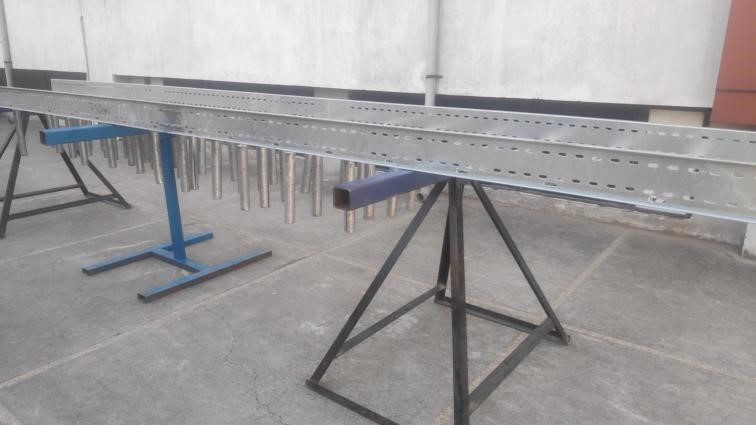
In electrical wiring of buildings, cable tray system is used to support insulated electric cables used for power distribution and communication. Cable trays are used as an alternative to open wiring or electrical conduit systems, and are commonly used for cable management in commercial and industrial construction. They are especially useful in situations where changes to a wiring system are anticipated, since new cables can be installed by laying them in the tray, instead of pulling them through a pipes.
Are you Looking for Cable Tray Testing laboratory?
If you are looking for cable tray testing laboratory in your area then your search will end at ITC India pvt ltd. ITC India Electrical Safety Testing Laboratory is doing Cable tray testing according to IEC standards. Capable Testing engineer are performing the testing with calibrated machines. So you need not to worry about the quality of testing. Here we like to mention the tests required to test cable tray and the Equipment required as per IEC 61537.
Scope of IEC 61537
IEC 61537 specifies requirements and tests for cable tray systems and cable ladder systems intended for the support and accommodation of cables and possibly other electrical equipment in electrical and/or communication systems installations. Where necessary, cable tray systems and cable ladder systems may be used for the division or arrangement of cables into groups. This standard does not apply to conduit systems, cable trunking systems and cable ducting systems or any current-carrying parts.
Material Classifications of Cable trays:
- According to material
- Metallic system component
- Non-metallic system component
- Composite system component
General Requirement and Testing
The general requirement of cable tray testing system and cable ladder system shall be so designed and constructed that in normal use, when installed as per manufacturer instruction, they ensure reliable support to cable contained therein. They shall not impose any unreasonable hazard to the user or cable.
First of all, classification is done and a test of marking and documentation is performed, in which the product is rubbed by soft hand with a cotton cloth soaked in petroleum spirit for 15 sec to check the durability of marking. All the documentation should be in compliance and inspection is done for this. All the dimensions are checked with the help of calibrated Vernier caliper and measuring tape.
Then all the tests related to clauses are carried out either by inspection or by manual tests as per requirement.
Cable Management System
Cable Management System is a management of electrical installation of Cables. Cables can easily become tangled, Products such as cable trays, cable ladders, and cable baskets are used to support a cable through cabling routes. It is management of Cable which gives support to cables for installation and prevent any accidental damage and Burn.
Types of Cable Trays and Ladders

TYPES OF FRP CABLE TRAYS
List of Critical Tests Conducted as per IEC/EN 61537
| S.no | Clause | Name of the test | Equipment used |
| 1 | 7.1 | Marking test | Water, Cotton cloth, petroleum spirit |
| 2 | 8 | Checking of Dimension | Vernier caliper, measuring tape, slide gauge |
| 3 | 9.3.1 | Mechanical tests on screwed connections | Slide gauge |
| 4 | 9.6-9.7 | Measurement of regular perforation pattern or regular rung pattern | |
| 5 | 10.3-10.4 | Deflection measurements at safe working load(SWL) | Climate chamber of minimum temperature and maximum temperature ( Table 2) |
| 10.7-10.8 | Load(SWL) | Slide gauge, tape measure, load plates of suitable length and shape, deflection measurement apparatus, fixid rigid support, cant | |
| 6 | 10.9 | Test of impact resistance | Pendulum Hammer |
| 7 | 11.1 | Electrical continuity | Electrical safety analyser |
| 8 | 11.3.4 | Humidity Treatment | Environment chamber |
| 9 | 13.1.2,13.1.3 | Contribution to fire and spread of fire | Glow wire test apparatus |
| 10 | 14 | Resistance to corrosion | Salt Spray test appratus |
| 11 | 15 | Electromagnetic compatibility | EMC machine |
Safe Working Load (SWL)Test:
- Test type I
Test type I shall be used when the manufacturer or responsible vendor does not declare any end span limitations and where the joints shall be placed on all installations. In this case, joints can occur anywhere on an installation.
- Test type II
Test type II shall be used when the manufacturer or responsible vendor declares that on all installations there shall be no joints in the end span. If the manufacturer or responsible vendor declares that on all installations the end span shall be reduced in length, the end span X shall then be declared.
- Test type III
Test type III shall be used when the standard cable tray length or cable ladder length is equal to the span or multiples of the span and the manufacturer or responsible vendor declares the joint position, relative to the end support, to be used on all installations. Test type III can also be used when the standard cable tray length or cable ladder length is 1,5 times the span and the position of the joint is at 25 % of the span from the support a. The test arrangement is shown in the figures below.
- Test type IV
Test type IV shall be used for products with localized weakness. In this case, the localized weakness is positioned over support b as shown in Figure 3. If this can be achieved by modifying test type I or II by moving the joint by up to ±10 % of L from its specified position, then this shall be done.
- Test type V
Multi-span test where the span is greater than 4m.
FAQs


