IEC 61547:2020
Equipment for general lighting purposes EMC immunity requirements.
CISPR 15:2018
Limits and methods of measurement of radio disturbance characteristics of electrical lighting and similar equipment
applies to the emission (radiated and conducted) of radio frequency disturbances from
- lighting equipment
- the lighting part of multi-function equipment where this lighting part is a primary function
- UV and IR radiation equipment for residential and non-industrial applications
- advertising signs
- decorative lighting
- emergency signs
What is EMC/EMI ?
EMI/EMC testing is a critical step in bringing a new product to market. Electromagnetic compatibility is the ability of electrical equipment and systems to function acceptably in their electromagnetic environment, similarly Emissions testing – measures the amount of electromagnetic noise generated by the device during normal operation. The purpose of these tests is to ensure that any emission from the device are below the relevant limits defined for that type of device.
What is the need of EMC/EMI Testing ?
The purpose of this EMC/EMI Testing is to Evaluate/Ensure that your product is capable to perform well without loosing its intended function in the presence of Electromagnetic Energy & It doesn’t emit a large amount of electromagnetic inference.
Major Product covered under IEC 61547:2020 & CISPR 15:2018
- Entertainment lighting.
- Advertising signs
- Decorative lighting;
- Emergency signs
- UV and IR radiation
- Lighting Equipment
- Rope Light
Name of Test under IEC 61547:2020 (Immunity)
| S No. | Port | Test | Standard |
| 1. | Enclosure | Electrostatic Discharge | IEC 61000-4-2:2008 |
| 2. | Enclosure | Radio Frequency Electromagnetic Fields | IEC 61000-4-3:2020 |
| 3. | Enclosure | Power Frequency Magnetic Fields | IEC 61000-4-8:2009 |
| 4. | Signal/control and load | Electric Fast Transients | IEC 61000-4-4:2012 |
| 5. | AC power | Electric Fast Transients | IEC 61000-4-4:2012 |
| 6. | DC power | Electric Fast Transients | IEC 61000-4-4:2012 |
| 7. | Signal/control and load | Immunity to Conducted Disturbances | IEC 61000-4-6:2013 |
| 8. | AC power | Immunity to Conducted Disturbances | IEC 61000-4-6:2013 |
| 9. | DC power | Immunity to Conducted Disturbances | IEC 61000-4-6:2013 |
| 10. | AC power | Surge Immunity | IEC 61000-4-5:2017 |
| 11. | AC power | Voltage Dips | IEC 61000-4-11:2020 |
| 12. | AC power | Voltage Short Interruptions | IEC 61000-4-11:2020 |
Evaluation of Test Results/Pass/Fail Criteria
To evaluate whether the product passes or fails in EMC immunity test, we need to monitor the equipment during and after each test and watch for any changes to the behavior or operation. The performance of the product usually falls into categories A,B,C and D.
The following four categories of performance criteria apply:-
Performance Criteria A:- That means the product performs normally and within specifications that specify, usually in the product manual, during and after the test. So essentially nothing bad happened to the product during or after the test.
Performance Criteria B:- The product may have had a temporary loss of function or degradation of performance which ceases after the applied disturbance ceases. So after the test finishes, the equipment under test recovers its normal performance without operator intervention. That just means that the operator didn’t have to do anything to get it back into a mode that it was in before the test started.
Performance Criteria C:- Is the same as B, but you’re allowed operator intervention as well.
So maybe you have to power the device back on. Maybe the EMC phenomena reset the device and you need to power it back on manually.
Performance Criteria D:- Is that there’s a loss of function or degradation of performance which is not recoverable, owing to damage to hardware of software or loss of data. So basically in some way the test has trashed the product. It might have fried some components or caused corruption of some data.
What is Conducted Emissions Testing?
The device creates electromagnetic energy and a certain portion of it will be conducted onto the power supply cord. In order to restrict the amount of interference your device can couple back onto a power supply, test labs measure these emissions (usually from 9 kHz – 30 MHz), and verify that they comply with specified limits. This helps to ensure that the local power supply remains relatively ‘clean’ and nearby devices won’t be affected by your device.
Major Equipment Used for Conducted Emissions Testing
- Line Impedance Stabilization Network (LISN)
- EMI Test Receiver
- RF Cable
- Attenuator
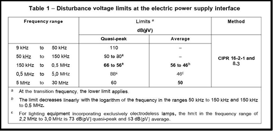
Limits and Methods for the Assessment of Wired Network Ports
Electric power supply interface
The limits and measurement method for the assessment of conducted disturbance voltages at the AC or DC electric power supply interface terminals for the frequency range 9 kHz to 30 MHz are given in Table 1.
Equipment under test configuration
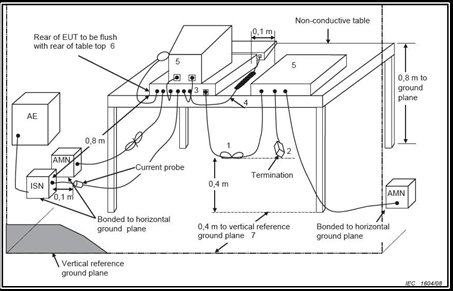
Typical Test Setup

What is Radiated Emissions Testing?
Radiated emissions testing involves measuring the electromagnetic field strength of the emissions that are unintentionally generated by the product into the air.
Types of Radiated Emissions Test Sites
- Open Area Test Site (OATS)
- Semi An echoic Chamber
- Fully An echoic Chamber
Major Equipment Used for Radiated Emissions Testing
- Loop Antenna
- Spectrum Analyser
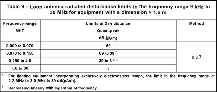
Limits and Methods for the Assessment of the Enclosure Port
- Enclosure port
Radiated-field disturbance limits in the frequency range of 9 kHz to 30 MHz.

Radiated-field disturbance limits in the frequency range 30 MHz to 1 GHz.
Equipment under test configuration.
