Surge
All electronic and electrical equipment are exposed to EMI such as ‘surge’. Surges are transient wave of current, voltage or power which rise rapidly followed by slower decline afterwards.
They are created by switching events and insulation faults in AC power distribution network, lighting and others. Surges are high voltages that contain significant amount of energy that can cause damages to the electrical and electronic devices.
Combination Wave Generators
Combination Wave Generators are used to simulate and generate the switching and lighting transients so as to evaluate the performance of the equipment when subject to high energy disturbances on the power and interconnect lines.
There are 2 specific types of CWG:
- 10/700 ms (voltage surge) 5/320 ms (current surge): This is for testing of ports connected to symmetrical communication lines.
- 1.2/50 ms (voltage surge) 8/20 ms (current surge): This is for testing of all other cases, such as short distance signal connections and power lines.
Surge Generator Calibration provides short circuit and open circuit waveform data that is then compared with the requirements listed in IEC 61000-4-5 i.e. the basic standard.


IEC 61000-4-5
IEC 61000-4-5 is the standard for surge immunity testing for electronic and electrical equipment. It relates to the immunity requirements, range of test levels and test methods for equipment with regard to unidirectional surges caused due to over voltages from switching & lighting transients.
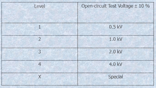
There are several test levels defined relating to different environments and installation conditions. These requirements are developed for and are applicable to electronic and electrical equipment.
The object of IEC 61000-4-5 is to establish a common reference for the purpose of evaluating the immunity of electronic and electrical equipment when subjected to surges.
This standard defines a range of:
- Test levels,
- Test setup,
- Test equipment and
- Test procedures.
The purpose of the mentioned lab tests is to find the reaction of the EUT under specified operational conditions to surge voltages caused due to lighting effects and switching.
It does not intend to test the capability of the EUT’s insulation to withstand high-voltage stress.
Features of 1.2/50 µs CWG
- Short circuit output current: 0.25 kA to at least 2 kA; +/- 10%; surge current waveform (8/20 µs).
- Open circuit output voltage: 0.5 kV to at least 4 kV; +/- 10%; surge voltage waveform (1.2/50 µs).
- Floating output.
- Phase shifting: 0° to 360°.
- Effective output impedance of 2 ohm.
- Repetition rate: At least 1/minute.
- Polarity: Positive/negative.

Peak Open Circuit Voltage and Timing of 1.2/50 µs CWG
| Test Voltage Setting kV | Voltage Surge Peak (±10% kV) | Front Time of Voltage Surge Peak (±30% µs) | Time to Half Value (±20% µs) |
| 0.5 | 0.5 | 1.2 | 50 |
| 1.0 | 1.0 | 1.2 | 50 |
| 2.0 | 2.0 | 1.2 | 50 |
| 4.0 | 4.0 | 1.2 | 50 |
Peak Short Circuit Current and Timing of 1.2/50 µs CWG
| Test Voltage Setting kV | Current Surge Peak (±10% kA) | Front Time of Current Surge Peak (±20% µs) | Time to Half Value (±20% µs) |
| 0.5 | 0.25 | 8 | 20 |
| 1.0 | 0.5 | 8 | 20 |
| 2.0 | 1.0 | 8 | 20 |
| 4.0 | 2.0 | 8 | 20 |
Verification of 1.2/50 µs CWG (6.1.2 of 61000-4-5)
- A measuring system with sufficient voltage and bandwidth capability
- Short circuit condition: Load ≤ 0.1 ohm.
- Open circuit condition: Load ≥ 10 kohm.

; Time to half value: T2 = 50 µs ± 20%
Features of 10/700 µs CWG
- Short circuit output current: 12.5 A to at least 100 A; +/- 10.
- Open circuit output voltage: 0.5 kV to at least 4 kV; +/- 10%; voltage surge waveform (10/700 µs).
- Repetition rate: At least 1/minute.
- Effective output impedance: 40 Ω +/- 10%.
- Polarity: Positive/negative.
- Floating output.

Peak Open Circuit Voltage and Timing of 10/700 µs CWG
| Test Voltage Setting kV | Voltage Surge Peak (±10% kV) | Front Time of Voltage Surge Peak (±30% µs) | Time to Half Value (±20% µs) |
| 0.5 | 0.5 | 10 | 700 |
| 1.0 | 1.0 | 10 | 700 |
| 2.0 | 2.0 | 10 | 700 |
| 4.0 | 4.0 | 10 | 700 |
Peak Short Circuit Current and Timing of 10/700 µs CWG
| Test Voltage Setting kV | Current Surge Peak (±10%) A | Front Time of Current Surge Peak (±20%) µs | Time to Half Value (±20%) µs |
| 0.5 | 12.5 | 5 | 320 |
| 1.0 | 25 | 5 | 320 |
| 2.0 | 50 | 5 | 320 |
| 4.0 | 100 | 5 | 320 |

